| < Previous page | Next page > |
Stage 1
For this tutorial we are going to do the initial design in DraftSight. Any general purpose CAD program can be used. DraftSight is used here as it is a free option.
You will need to download and install DraftSight before following this tutorial.
Stage 1:
Open up DraftSight and you are presented with a blank screen. Most CAD programs are dimensionless and in this example we are going to design in millimeters. You could just as easily do the design in meters or decimal feet.
The carport consists of a concrete slab. There are going to be 6 posts. There are two beams running lengthways. On top of these we have cross beams that support a simple truss designed roof. The roof is going to be corrugated iron.
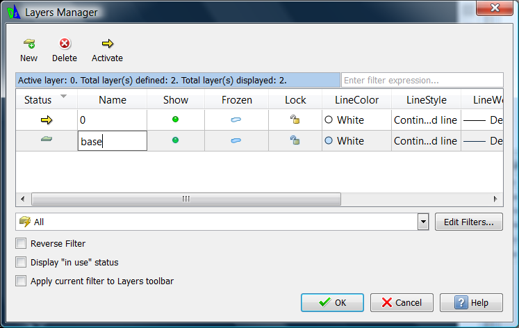
First step is to draw in a concrete slab. Before doing this we are going to define a new layer which the block is to sit on. From the Format menu hit "Layer" menu item and the "Layers Manager" dialog is displayed as below. Hit new and create a new layer called "base".
We now wish to draw in the base which we have designed as a 6 by 3 meter base. We are going to assume the lower left of the slab is positioned at 0,0.
Within DraftSight click in the "Draw" and then "Draw Rectangle". Specify a start corner of 0,0 and an opposite corner of 3500,6000.
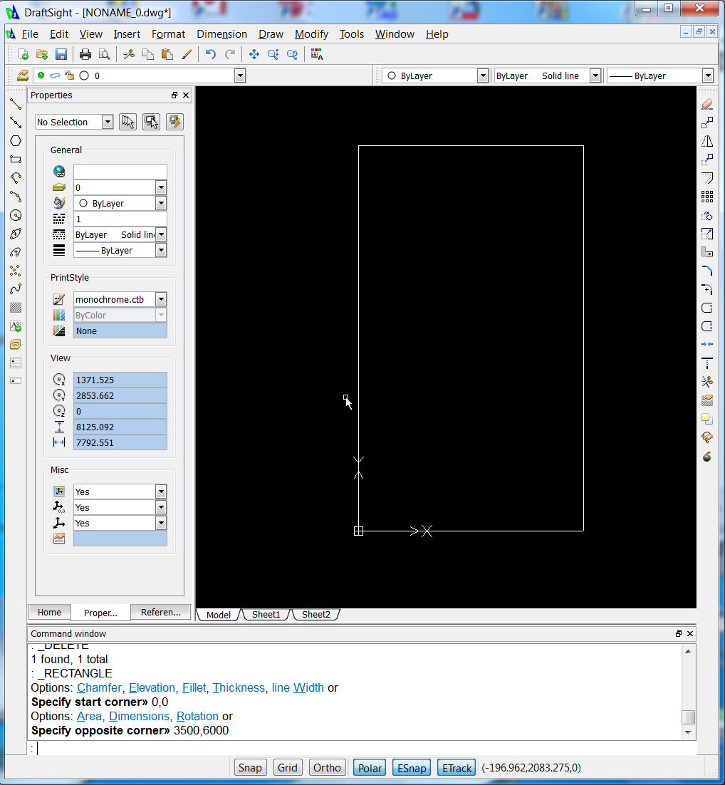
You will see the concrete base drawn.
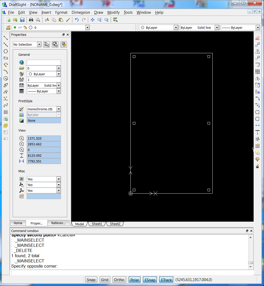
We are now going to place the 6 supporting posts. Again create a new layer and we are going to call the layer posts. Insert the posts 100mm in from the base edges. The post lower left will start at 100,100 and as it is a 100mm post the end corner is 200,200. Again use the Draw - Draw Rectangle option. Rather than draw the same thing 6 times we are now going to copy the entity. They have a Y displacement of 2900mm and an X displacement of 3200.
Left click on the existing post and go Modify - Copy. Use start point of 0,0 and end point of 3200,0.
Now hit the escape key and select both posts by left clicking them. Again use the Modify - Copy and use a start point of 0,0 and then a 2nd point of 0,2850. Use another second point of 0,5700 and you will have the design below.
So we can see where we are going without too much effort we are now going to save what we have and convert into sketchup. From the File menu select "Save" and save to a file called "carport.dwg". I suggest you use the "my documents/ezicad" directory. Close down the DraftSight program.
Ezicad
Now open up Ezicad and from File - Open menu display the same drawing file just saved. Again we have the concrete block and the six posts displayed. We are now going to bring up a table that allows us to specify how these elements are to be displayed in 3 Dimensions.
From the File menu click on the "Export Sketchup" option.
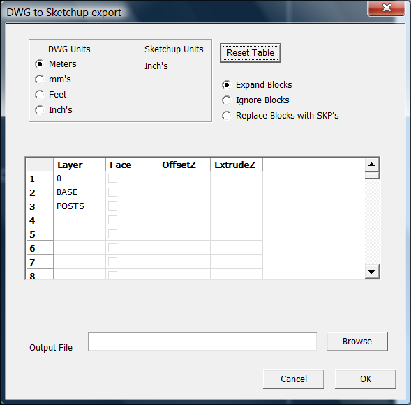
Click on the "Reset Table" button and the table will display the layers within the job.
We can ignore layer0 as there are no entities on this layer.
If we look at layer "BASE". This layer contains the concrete base. It will stay on the Z axis but we wish it to be 100mm thick. Add in a "ExtrudeZ" value of -100. For the posts we want them to be 2400mm high. Again the z value is on the ground and ExtrudeZ value is 2400. See the table below for the values:
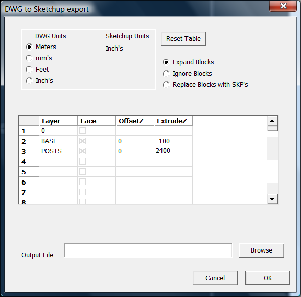
Now browse to an output file - we are going to call it carport.skp and hit the OK button.
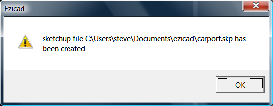
A message box is displayed when sketchup file is created.
Check in SketchUp
Now open up Sketchbook and open up the carport.skp file. You will see that we have the concrete base as well as the 6 posts displayed as below:
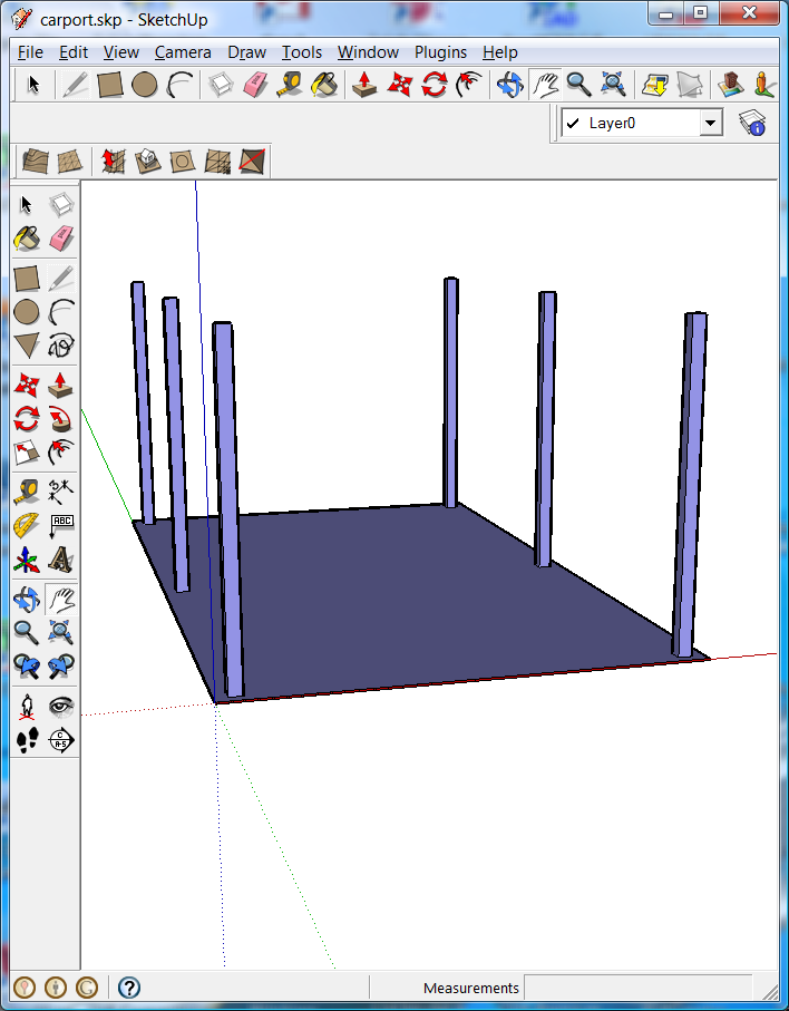
We will continue with the same basic procedure in stages 2 and 3 to fill out our model. If some of the entities are not rendered properly go back into Ezicad or DraftSight and check whether the base and the post are on the appropriate layers.
|