| < Previous page | Next page > |
Stage 2
In stage 2 we are going to add in the following components:
2. 100*50 crossways beams spread apart at 450mm
Reopen the drawing in DraftSight. We need to draw in the two lengthways beams. As before create a new layer from the Format - Layer option and call it layer "mbeam". Add in the left beam using the Draw - Draw Rectangle command. The left corner is at 100,100 and the right top corner at (150,5900). As before do the Modify - Copy command and copy and move beam a distance of 3250. Ie use start point of 0,0 with an end point of 3250,0.
We now need to add in the beams that sit on these main beams that run across the shed. We also want them to overhang 100mm. We can put in the initial beam : using draw - draw rectangle command. The left point is at 0,100 and end point is at 3500,50.
As before we will copy and move this beam up. The distance between beams is 450mm. The finalne will be slightly shorter. So using the Modify - Copy routine; select the first beam and use 1st point of 0,0 and a second point of 0,450. Then next use 0,900 - 0,1350 etc
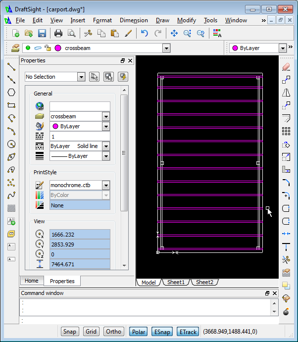
The cross-beams are shown in Magenta above.
We also wish to place the beams that hold up the roof. Simply draw in the top view as before and we will modify the start and end height in Ezicad. However remember the height is highest in the center and drops on both sides. To achieve this we will need to put the left and right side beams on different layers.
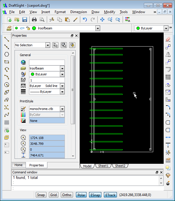
These roof beams will also overhang the cross beams by an extra 100mm. Doing the left hand side first. We initially create a new layer called "lroofbeam". We will set this color to green. Now draw the initial roof beam by "draw" - "draw rectangle" command. The initial beam has left start position of -100,100 and right position of 1750,50. As before we need to copy every 450 up. We get that seen below.
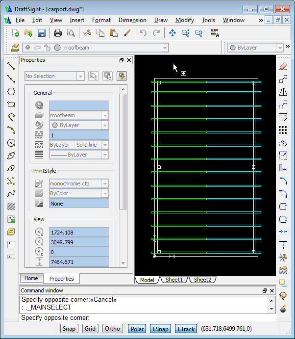
We now need to do the right hand side. Again create a new layer, we will call it rroofbeam and select all these beams and then copy it across.
Time to get an idea in 3D. Save the file from DraftSight and close down DraftSight. Open up the file in Ezicad.
Once in Ezicad click on the "File" - "Export Sketchup" option. We need to fill in the table with the additional data.
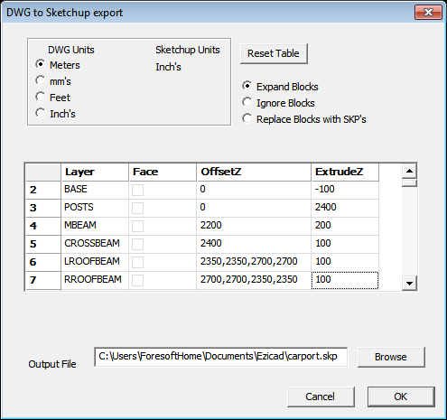
If you look at the "mbeam" layer you can see that we have raised the entities 2200mm and then extruded it 200mm to make the beam. The "crossbeam" layer is handled in a similar manner.
Now for the slightly more tricky roof beams. If we look at the left side we want to raise the left side a distance of 2350 and the middle a distance of 2700mm. If the entity does not have a constant offset then we can specify an offset for each individual point making up the entity. DraftSight creates the rectangle in a clockwise direction. If you get the order wrong - simply check in Sketchup and modify accordingly.
For the right side roof beams we simply change the order.
Make sure an output file is specified and hit the "OK" button.
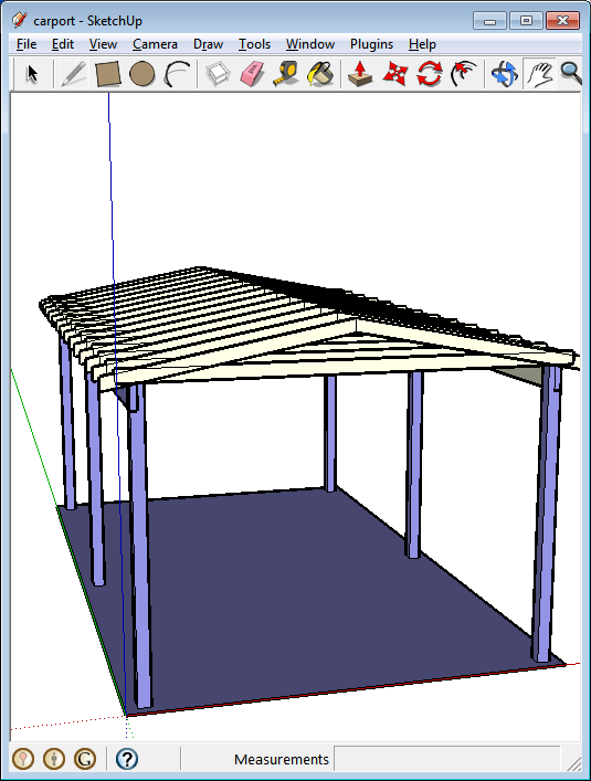
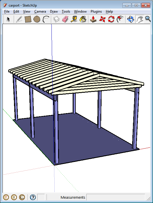
The design is shown above. You will notice that the roof beams need to be raised. Simply go back to Ezicad and rerun the File - Export to Sketch routine - until you get as below.
 |